Hospital Substation Gas-insulated Switchgear

Located in Toronto, ON, Sunnybrook Health Sciences Centre is a full-service hospital with over 1,300 beds, making it the largest regional trauma centre in Canada. Through its partnership with Veterans Affairs Canada, it is home to more than 500 veterans. With a main campus of approximately three million square feet, Sunnybrook is redeveloping its existing main outdoor electrical substation in its
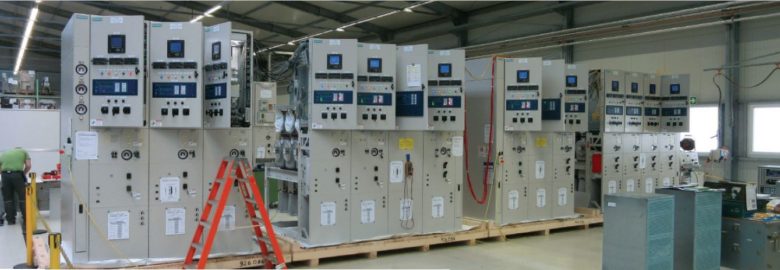
entirety. The project incorporates several innovative features, including using 38 kilovolt class gas-insulated switchgear, new power transformers with increased capacity, and multiple civil upgrades. In addition to a decreased footprint and reduced maintenance requirements, the new switchgear interfaces with a networkbased monitoring and control system. In this photo, the switchgear undergoes indepth factory acceptance testing in Frankfurt, Germany.

Sunnybrook team: Michael McRitchie, Francis Jesuthasan. Prime consultant, H.H. Angus & Associates Ltd.: Philip Chow, P.Eng.

Hovering Autonomous Underwater Vehicle

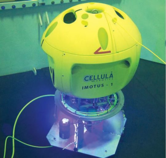
In fall 2017, Cellula Robotics Ltd. successfully demonstrated its Imotus-1 Hovering Autonomous Underwater Vehicle. During a week of testing at a local pool facility, Imotus-1 navigated using proprietary Simultaneous  Localization and Mapping (SLAM) algorithms and was shown to hold station, waypoint track, manoeuvre around obstacles, and dock to an underwater charging station. The docking demonstration was sponsored by Ocean Networks Canada; development of SLAM was made possible through funding from the National Research Council’s Industrial Research Assistance Program. In 2018, Imotus-1 will be used by Cellula in the North Sea for commercial survey and inspection work inside the structural legs of an offshore platform.

Eric (James) Jackson, P.Eng., Melanie Devaux, P.Eng., Paul Prunianu, P.Eng., Dr. Peter Hampton, EIT, Dana Leslie, EIT, Jacqueline Nichols, P.Eng.

Novel Polystyrene Recovery System

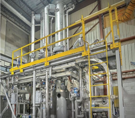
A.H. Lundberg Systems Limited of Vancouver designed and supplied a modular distillation system for Polystyvert for its polystyrene (Styrofoam) recycling demonstration plant in Montreal. In a novel patented process, an essential oil is used to dissolve the polystyrene at the user site, thereby drastically reducing the volume and subsequent transport costs to the recycling plant. Following recovery of the polystyrene using a liquid hydrocarbon, the distillation system separates and recovers the essential oil and hydrocarbon for reuse in the process. The module was fabricated and assembled by Acier St-Michel in Laval, QC. The plant is scheduled for commissioning in May 2018.

Allan Jensen, P.Eng., Bruce Der, P.Eng., Alex Lisnevskiy, P.Eng.

Published in Innovation Magazine 
Engineers and Geoscientists British Columbia
May/June 2018

HH Angus is engineering mechanical and electrical systems for three underground stations on the Metrolinx Eglinton Crosstown Light Rail Transit project – Mt. Pleasant, Bayview and Laird Stations. The ECLRT will run along a 19 kilometre corridor following Eglinton Avenue, including a 10 kilometre underground portion. Click here, to see the latest tunnel fly through video.

Meeting  stringent standards while reducing energy use.

Hospitals face unique design challenges in meeting air handling requirements, none more so than the special requirements of operating rooms. As lighting systems and building  envelopes have become more energy efficient, it is air handling systems that increasingly  represent a hospital’s greatest energy consumer. But there are options to mitigate the energy demands of these systems.

Air handling systems are an important part of any building for maintaining occupant comfort. When it comes to hospitals, there are a series of special requirements that make ventilation systems critical to the delivery of healthcare.

Firstly, air handling systems are relied on to help protect occupants and adjacent  surroundings from infectious diseases and hazards created by equipment and processes. Many contaminants are generated which must be exhausted. In many areas of a hospital, the systems are designed so that air flows from clean to less clean areas to help protect staff and other occupants. A good example of this is Airborne Isolation Rooms where differential pressures must be monitored and alarmed.

Air handling systems are also a key component of the life safety strategy for managing smoke in a fire situation. A measure of the reliance on air handling is the requirement that ventilation systems must limit smoke concentration to allow operations to be safely concluded or for critical care patients to be safely transferred.

And now the rising level of patient acuity and the pressure of high utilization, with occupancy rates well above 100%, are putting even more pressure on HVAC systems. In Canada, CSA Standard Z317.2, Special  requirements for heating, ventilation, and air-conditioning (HVAC) systems in health care facilities, is referenced in most if not all Canadian Building Codes as good practice for the design, construction and operation of air handling systems. The latest edition was published in December 2015, and work  recently started on the next version due in 2020.

Operating rooms

Operating rooms and similar spaces where invasive procedures are performed have a number of particular air supply requirements:

  • Common practice for operating rooms is to supply a high volume of air at low velocity through laminar flow ceiling diffusers in the central area of the room with the intent of achieving a piston effect. The intent is for air to generally flow first past the patient and clean surgical staff before flowing to the outer portions of the room to the exhaust grilles. Studies have shown that 20 air changes per hour is effective; note, this is a far cry from the hundreds of air changes of a true laminar flow clean room.
  • The cleanliness of operating rooms is critical. Standards call for the supply air to be filtered to at least MERV 14, but many engineers and facility managers look to increase this to a higher level. HEPA filters, which are rated to 99.97% efficiency on 0.3 micron particles, have been adopted as the standard in many cases.
  • Staff generally prefer operating rooms be kept relatively cool as they are often gowned in multiple layers to minimize the possibility of infection. The premise that a wide range of temperatures is necessary to control the temperature of the patient, particularly during cardiac surgery, is not well founded. Blankets or pads that heat or cool are used to control the patient’s temperature.
  • There has been great debate over humidity in operating rooms. Many years ago the anaesthetics in use were flammable, and operating room  humidity was maintained between 50% and 60% to minimize the possibility of static electricity discharge. As anaesthetics became safer, the low end of the humidity range was reduced to 40%. The initial concern was that less humidity would cause drying at the surgical site; however, this condition was not observed. In the 2015 version of CSA Z317.2, the lower humidity limit was lowered to 30%, similar to most other spaces in a typical hospital.
  • Design engineers must carefully analyze the psychrometrics of air supplied to operating rooms over the possible range of temperature and humidity conditions. This is particularly true in the summer when cooling coils are relied on to dehumidify moist outdoor air. If this air is not dry enough, the relative humidity limit in operating rooms kept at a cool temperature will not be maintained. Enhanced cooling coils, lower chilled water temperatures, and desiccant moisture removal are some of the solutions.
An operating room inside the Centre hospitalier de l’Université de Montréal.

Energy efficiency

These high levels of ventilation and air cleanliness, coupled with stringent temperature and humidity control and around-the-clock operation, all contribute to high energy use in hospitals; however, there are a number of strategies that can help reduce energy use:

  • Moving air at lower velocities takes less energy, so air handling equipment and ductwork with a larger cross sectional area needs less fan power to move the air.
  • Variable volume air supply and exhaust is more complex in a hospital due to the requirement to maintain directional airflow between most rooms and departments. This generally requires that each individual room or group of rooms control both supply and exhaust air in tandem so pressure relationships can be maintained.
  • A number of methods of heat recovery, when correctly applied, have proved effective while maintaining the cleanliness of the air. Projects such as the Centre hospitalier de l’Université de Montréal (CHUM) and Royal Jubilee Hospital in Victoria used enthalpy heat recovery wheels on all air handling systems to transfer heating, humidity and cooling from the exhaust air to the supply air.
  • There is a misconception that air handling systems all need to operate 24 hours a day. This is true for a number of space types but, even in more critical spaces, there are opportunities to reduce the total air volume or volume of outdoor air when the spaces are not in use, as long as certain conditions are met. Less critical areas offer more flexibility to reduce airflows or setback temperature setpoints.
Interior of the Royal Jubilee Hospital in Victoria, where enthalpy heat recovery wheels are used on all air handling systems to transfer heating, humidity and cooling from the exhaust air to the supply air.

Published in the Canadian Consulting Engineer
January/February 2018 

Author

Nick Stark, P.Eng., CED, LEED® AP, ICD.D
nick.stark@hhangus.com

cover photo of article

Does  your facility have a game plan to remain operational during an unexpected outage?

Stories of mass disruptions caused by electrical power outages make front-page news. We hear about extreme weather events, such as Hurricanes Katrina (2008) and Sandy (2012) and the Ontario Ice Storm of 2013 that cause widespread power outages due to damaged electrical utility infrastructure. International airlines have experienced disruptions with a multitude of stranded passengers due to electrical outages in the data centres that manage bookings. Cybersecurity and physical security have also become prevalent subjects with the continuous expansion of networked systems and recent acts of hacking and terrorism around the world. While difficult to quantify, executives understand the impact power outages have on corporate revenue, restart costs and poor public image with customers.

In the event of an unexpected electrical power outage, does your facility have a game plan to remain operational and restore systems? Does your operations group have a program that maintains emergency preparedness for electrical outages?

Internal power outages originating within a facility can be both short-term and long-term events. Short-term outages typically result from nuisance tripping, where overcurrent protection de-energizes a circuit due to an abnormal event, an increase in electrical load, the addition or replacement of equipment with new ratings, or incorrect protective settings. In most instances, short-term outages do not result in any significant equipment damage, and power is restored after the cause is identified and subsequent diagnostic tests are performed. Long-term outages can result from a variety of causes and typically result in permanent equipment failures and damage that renders a portion of a distribution system inoperable. When a long-term outage occurs, facilities fortunate enough to have redundancy built into their distribution system can rely on alternative feeders, transformers or circuits with spare capacity to restore power in the interim. Without the luxury of built-in redundancy, temporary solutions and temporary equipment rentals may be required, while replacement equipment is being manufactured (a process that can take upwards of 20-plus weeks). In order to fully appreciate the possibility and impacts of unexpected internal power outages, let’s consider a few case studies.

Short circuit

Electrical work can create the potential for electrical hazards, accidents and associated power outages. In this case study, an electrical contractor was expanding on a newly installed 15,000V (15kV) distribution system. A dedicated electrical-service space was being constructed in a critical, process-based facility in British Columbia. The contractor was in the process of running a 15kV feeder circuit to connect an existing load to the new distribution system and new medium voltage cables had been run in anticipation of an upcoming shutdown to make the final connections. Prior to the shutdown, the contractor was performing some final checks within the 15kV switchgear and accidently energized the 15kV circuit. The new MV cables, which were left unterminated and coiled together, became energized and created a three-phase bolted fault. The accidental energization resulted in a short-circuit event of about 10,000A and was near the maximum fault level stipulated by the local utility. Multiple medium voltage circuit breakers tripped as a result of the fault, including a main breaker in the service entrance switchgear for the site. The facility’s standby generators came online, due to the tripped circuit breakers and powered the facility for a number of hours, until the a procedure to properly isolate the circuit was implemented and utility power was restored. Fortunately, no injuries occurred and a subsequent assessment revealed that no damage to equipment or cables occurred, with the exception of the cable ends, which were cut back several inches.

Failed transformer

Facilities often rely on service groups to perform routine electrical tests, circuit switching and isolation requests. The exact switching procedure is typically left up to the service group and they are responsible for operating distribution equipment. In this case study, a service contractor was manually switching between utility power and standby generator power via a set of 480V circuit breakers. The system was placed into manual operation, utility power breakers were opened, standby generation was brought online and generator breakers were closed to provide power to the switchboard. When it came time to return to utility power, the utility power breaker was inadvertently closed, while the standby generators were still powering the switchboard. The switchboard did not have any synch-check protection, paralleling equipment or interlocks. The individual generator breakers tripped open several seconds after the unintended paralleling condition was created. Unfortunately, large magnitude currents had circulated within the distribution system, before the generator breakers tripped. These large magnitude currents created significant magnetic forces, which damaged bus work in a dry-type transformer that was close coupled to the switchboard. The bus work was bent outwards and insulating paper covering a portion of the bus was dislodged, creating a condition where uninsulated bus was bent into contact with the grounded steel frame, supporting the core and coil assembly. The resulting line to ground fault melted the entire bus connection, until the phase to ground fault was eliminated and the bus connection was no longer in contact with the steel frame. Fortunately, proper safety procedures had been followed and no one was injured in this incident. The switchboard was supplied with power from a redundant transformer and the damaged transformer was permanently removed from service. The facility subsequently shifted downstream loads to other distribution within the building, to further offload the remaining transformer.

Latent installation defects

Electrical failures can also occur unexpectedly within a distribution system, without any precipitating factors such as electrical work or switching operations. A variety of recent cases come to mind, with causes that include latent installation defects, utility supply issues and failures related to aging electrical infrastructure. A critical facility, in the Greater Toronto Area, experienced a localized extended power outage for several weeks, when a dry-type transformer unexpectedly failed. The dry-type transformer provided essential power to both occupied areas in the building and critical process-based loads. The transformer had been recently upgraded to a new energy-efficient model and the replacement core and coil assembly had been site installed, due to space limitations and access requirements for a newly manufactured unit. The failure analysis confirmed that low-voltage control wiring for power metering had been installed in close proximity to uninsulated 5kV buswork and a flashover had occurred due to the insulation rating of the wiring and insufficient physical clearance. Operations were shut down in the affected area until a refurbished transformer was sourced and installed.

In another example, an Ontario- based electric utility experienced an outage to one phase in a distribution circuit, when parallel fuses for one of the phases in a disconnect switch unexpectedly blew. The utility replaced the blown fuses and restored power within several hours. However, by this time the facility had determined that several 30 hp motors, critical to the central plant’s chilled water and condenser water system, had burned out due to the single-phasing condition and inadequate motor overload protection. Mechanical services were interrupted for 15 hours while motors were replaced. In yet another example, an underground 5kV distribution cable, in an institutional campus, unexpectedly failed after approximately 25 years in service. Temporary generators were brought in for a week, until a portion of the failed cable could be removed and re-fed with replacement cable. While the cable had not yet reached statistical end-of-life conditions, it was determined that the early failure was attributed to physical damage, which had reduced the cable’s anticipated life expectancy.

Modes of failure

How can an operations manager plan for an unexpected electrical outage in their facility? To start, a well-structured preventative maintenance program and an infrastructure review can help diagnose potential risks. Is equipment being maintained and are recommended diagnostic tests being performed? Equipment should be reviewed for age and reliability. Consideration should be given for redundancy in the power distribution system and how the failure of a particular component could affect continued operation. Taking meter readings on a frequent basis will confirm if there has been any load growth and how load is segmented throughout a distribution system. If metering is unavailable, consideration should be given for installing permanent metering or taking readings with a portable meter. Operational data can be used to expand on a facility’s electrical single-line diagram and performing a detailed review can determine options for supporting load in emergency situations. Emergency scenarios should include how critical loads are supported during an extended utility outage, how load can be supported during equipment failures (transformers, switchboards, panels and main feeders), points in a distribution system for connecting a temporary generator and options for interlocked tie connections. Abbreviated single line diagrams for modes of failure and electrical load data can be used to create a standard operating procedure (SOP), in the event of an unexpected power outage. A well-developed SOP will include detailed, step-by-step operations to help diagnose an electrical outage, isolate faulted equipment if applicable and restore power using alternative means, if available. Photographs of equipment should be included and operating switches, buttons and HMI screens should be identified. Having a guide readily available will increase response times and decrease downtime.

Plan ahead

To complement the effectiveness of standard operating procedures, any work performed on a power distribution system should be subject to a detailed method of procedure (MOP). A typical MOP will outline a step-by-step procedure for work being performed and includes information on demarcation of work (who is doing what?), the duration of tasks, a back-out plan to deal with the unexpected occurrences and a list of emergency contacts. A dry-run of switching operations and load transfers should be performed in advance of a planned shutdown, especially when a number of complex switching operations and load transfers are involved. Operations staff should actively participate in the process, as this will further develop familiarity with a power distribution system and mitigate risk when electrical work is being performed. Consideration should also be given to providing regular training sessions on electrical systems for operators. Training should focus on the topology and equipment in the distribution system, facility procedures (SOPs and MOPs), preventative maintenance requirements and general troubleshooting practices. Having well-trained operations staff will not only ensure that a facility’s first responders can effectively deal with issues when they arise but also ensure outside contractors follow an approved procedure before commencing work.

Unexpected electrical outages in a facility can be caused by a variety of factors, including electrical work, routine switching operations, issues with the incoming utility supply, or aging infrastructure. A proactive approach to managing an electrical power distribution system and maintaining emergency preparedness should include: a well-developed preventative maintenance program; the creation of SOPs to identify an approved response to emergency scenarios and to troubleshoot issues; MOPs for all electrical work, including preventative maintenance and isolation procedures; and having regular training sessions for operations staff. Undertaking a detailed needs assessment will help a facility review procedures currently in place, identify any shortcomings with existing practices and provide opportunities for improvement. Creating documentation for SOPs, MOPs and training will typically involve a detailed review of existing systems, creating a site-specific set of procedures, and drawing upon industry standards and best operational practices. By investing in a plan for emergency preparedness, operations managers can equip their staff with the knowledge to deal with the next electrical outage, thereby increasing response times, decreasing downtime and ensuring their facility remains operational.
Published in the Canadian Consulting Engineering Magazine September 2017 Page 23-24. 

Authors :

Phil Chow, P.Eng., P.E., Senior project manger & electrical engineer at HH Angus

Mathew Walker, P.Eng., Senior electrical engineer at TELUS Communications

High-resistance grounding provides safer, more reliable electrical distribution for healthcare facilities

High-resistance grounding is relatively simple and easy to apply in radial distribution systems. It has been used in the healthcare industry for many years, considered to be “best practice” for hospitals. The concept is well-known, recognized by the Canadian Electrical Code, and driven by four basic factors: power is not interrupted in the event of a single ground fault; negligible damage at the point of fault, resulting in lower repair costs and faster return of equipment to service; negligible arc flash hazard in the event of a single ground fault; and negligible risk of a single ground fault escalating into a damaging line to line or three phase fault.

It is best practice to have the low voltage (600V) and high voltage (4,160V) systems equipped with high-resistance grounding. This has often taken the form of a neutral  grounding resistor applied between transformer neutral and ground. An alarm is raised on the occurrence of a ground fault in the distribution as required by the installation codes. In modern relays, the zero-sequence sensor signal causes a pick up; then the simultaneous presence of unbalanced voltage to ground is verified before an alarm is indicated. To avoid the possibility of nuisance alarms caused by inrush currents and non-inear loads, the zero-sequence current sensor output is filtered and only the fundamental signal is extracted. These measures have been effective in avoiding nuisance alarms and trips in sensitive ground fault relays.

The primary benefit of using high-resistance grounding is the faulted feeder does not need to be isolated on the occurrence of a phase to ground fault.

Vantage Point

The use of high-resistance grounding offers many benefits.

Arc flash and blast hazard for a line to ground fault is prevented. For systems up to 4,160V, where the resistor let-through current is 10A (amperage) or less, the arc blast is unlikely. Such systems can continue to operate with one ground fault. The fault does not escalate so the distribution system is safer. Accidents causing line to ground faults will not produce a hazardous blast or arc flash.

Fault damage at the point of fault is very low and can be easily repaired. It minimizes maintenance repair costs. Motor and generator laminations will not get burnt and winding repair costs will be small.

For systems up to 4,160V, where the resistor let-through current is 10A or less, the line to ground fault can be kept on the system continuously. No fault isolation needs to occur per Canadian Electrical Code 10-1100 through 1108.

Damaging voltage transients that can occur on ungrounded systems are avoided since the system is grounded.

On the other hand, four application concerns arise when resistance grounding is applied to distribution.

All cables need to have a line to ground voltage rating of line to line voltage for the maximum duration of the line to ground fault. This is not an issue at low voltage, such as 600V. The standard cables have adequate ratings.

Lightning arrestors and surge suppression devices that are connected line to ground also need to be adequately rated.

Voltage to ground impressed on capacitors will also increase to line to line value.

The circuit breakers and contractors employed in resistance grounded systems must be able to break L-L voltage across one pole of the device. For example, a three pole 600V breaker must be able to open fault current and withstand 600V across one pole, which most 600V breakers are capable of. However, some breakers only have a 347/600V rating. This  means they are able to interrupt only 347V across one pole, making them unsuitable. The same would apply to contractors.

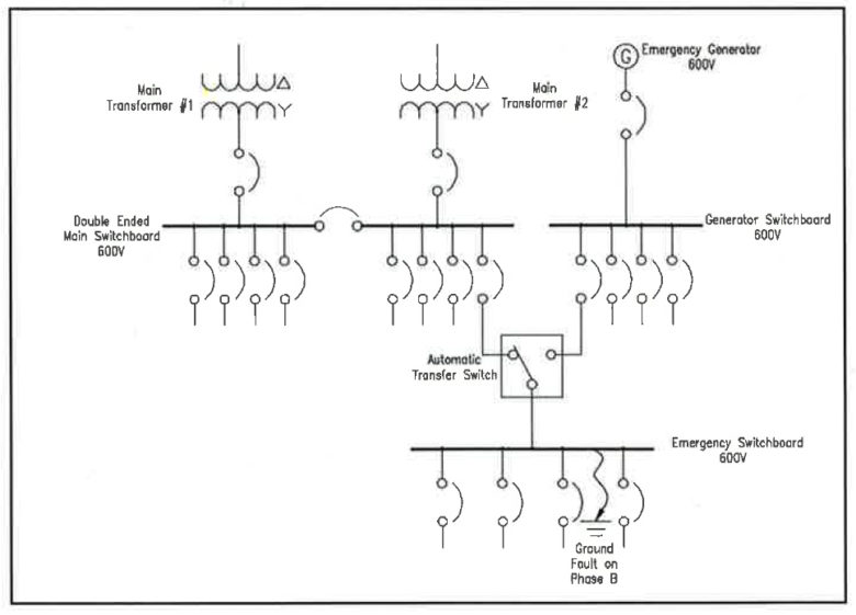
In this scenario, a ground fault occurs in the switchboard downstream of a transfer switch.

Fault Scenario

In a typical hospital, there will be a 600V normal power system and a 600V generator power system. The most critical loads are fed from the emergency power distribution, which is downstream of one or more transfer switches. The transfer switches get power from both the normal power system and the generator power system. In this scenario, a ground fault occurs in the switchboard downstream of a transfer switch. This fault could have a number of causes.

In the solidly grounded system, the ground fault results in a large current flow creating significant damage within the switchboard, vapourizing components and coating the inside of the switchboard with semiconductive residue. The high fault current subjects the upstream transformer to high stresses and causes the upstream breaker to trip. All power to the critical loads is lost. The loss of power is sensed at the transfer switch, which starts the emergency generator and transfers the critical load over to the generator. Since the switchboard is contaminated with residue from the previous fault, another fault occurs and this further damages the switchboard. It also stresses the generator with a high magnitude fault current and causes the generator breaker for the transfer switch to trip. The critical loads, including the emergency department and intensive care unit, are shut down and remain so until their feeders can be cut away from the failed switchboard, spliced and extended to another source of power – a process that takes many hours and leaves the critical loads on normal power only. The hospital is forced into emergency mode and must transfer critical patients to other areas of the hospital, which were not designed for their care, and in some  cases to another hospital. Full restoration of the system requires replacement of the switchboard. This takes many months as switchgear is built to order.

In the resistance grounded system, the ground fault results in an alarm. There are no power interruptions, the main transformer is not subjected to the stresses of a fault, and the generator does not start, and is not exposed to a fault current. Most importantly, the damage to the switchboard is minimal, requiring the replacement of a single insulator, which is scheduled for a time when the hospital can accommodate the short shutdown necessary to perform the work.

Ground Current Detection

A major functional enhancement occurs when detection and alarm of ground faults is supplemented with monitoring of all the feeders to indicate which feeder is faulted and administer assistance for quickly locating the fault.

To provide assistance in locating a fault in highresistance grounded systems, the fault current is modulated by oscillating it between values such as 5A-10A, typically at one cycle per second. This is accomplished by changing the resistor value using a contactor, which has been called ‘pulsing’ in the industry. The  pulsing is manually started. A flexible zero-sequence sensor or a clamp on the current transformer encircling all phase conductors is used to provide an oscillating signal to a handheld multimeter. Readings are taken on the faulted feeder moving away from the switchboard. The signal will disappear once the fault location is passed. Often, two or three measurements are sufficient to point to the fault location. Readings are taken from the outside of the grounded raceways, conduits or busways, while the system is energized and running. This technique has been in use for many years. It is quite effective for voltages up to 4,160V.

Tripping Up

The primary benefit of using high-resistance grounding is the faulted feeder does not need to be isolated on the occurrence of a phase to ground fault. While the faulted system continues to operate, there is a possibility that another phase to ground fault may occur on a different phase in some other weak spot in the distribution system. With the presence of a second fault, the fault current is no longer limited by the resistor and will be a higher magnitude fault. The zero-sequence sensors continue to monitor the fault current and if a significantly higher current than that limited by the resistor is detected, then the system recognizes that a line to ground to line fault  exists and identifies the two feeders involved. Only one feeder breaker needs to be tripped to revert the rest of the system to a single fault condition. A level of priority can be assigned based on the relative importance of the feeders. The one feeder with lower priority is tripped. Fast operation provides protection and minimizes fault damage. Such systems have been in use for a long time and this first fault alarm and second fault trip is best applied to monitor specific loads.

Improving the System

On low voltage systems and systems up to 5 kilovolt (kV), high-resistance grounding  provides a safer and more reliable distribution system. The arc flash hazard in the event of a line to ground fault can be eliminated and power continuity maintained. The  performance of the distribution system can be enhanced by using high reliability neutral grounding resistors with low temperature coefficients, monitoring the neutral ground resistor continuously, using a pulsing system to find ground faults and using coordinated selective second fault tripping. In many applications, it is more beneficial to apply the neutral grounding resistor at the main bus. In such a case, the incoming supply feeders can be monitored for ground fault very cost-effectively by applying multi-circuit relays.

Authors

Ajit Bapat, P.Eng., Owner of Power Solutions
Nick Carter, P.Eng., Principal at HH Angus & Associates Ltd.
Sergio Panetta, P.Eng., Vice-president of engineering at I-Gard Corp.