Marketable vs. sustainable – why not both?
The building envelope defines the building’s aesthetic while establishing the basis for the building’s overall energy and carbon performance. Despite its importance, teams often design based on what is “marketable” at the expense of thermal performance and then rely heavily on the mechanical and electrical systems to compensate for the performance gap. This practice is especially true with Multi-Unit Residential Buildings (MURBs) and some commercial building where high window-to-wall ratios are perceived as more desirable.
...it is possible to design buildings with high-performance envelopes that can be perceived as both desirable and sustainable.”
A lower performing envelope typically translates into higher MEP capital costs and increased operational costs over the life of the building (e.g., higher natural gas and electricity bills). The building envelope thermal performance is a critical consideration for reducing space heating loads, as space heating is a primary source of GHG emissions for commercial, institutional, and residential buildings . Consequently, high-performing building envelopes play an important role in reducing the carbon footprint of buildings.
With collaboration between the design team disciplines, it is possible to design buildings with high-performance envelopes that can be perceived as both desirable and sustainable. As the industry moves towards low-carbon designs, these buildings could arguably become even more “marketable” given their sustainability achievements.
“Effective” thermal performance and HVAC systems
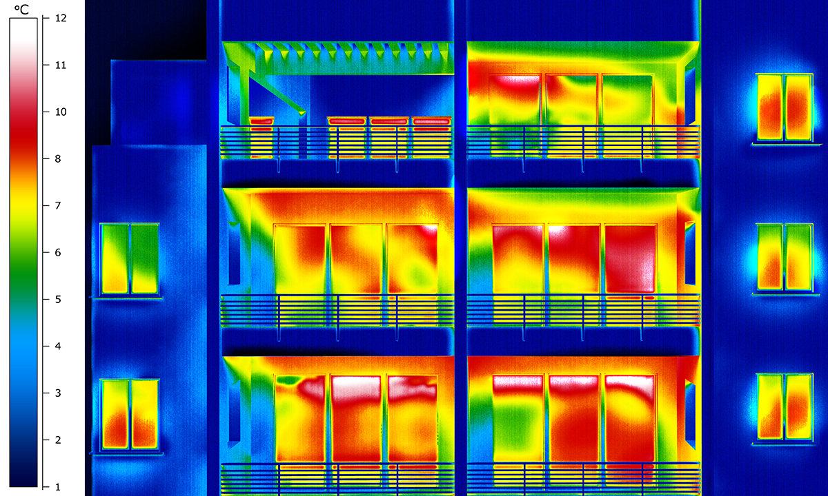
One aspect of building envelopes that has historically been underestimated is the effect of thermal bridging on the effective thermal performance of different constructions, which directly impacts the HVAC sizing process. Overestimating the envelope thermal performance can lead to under-sizing of equipment and to uncomfortable indoor conditions. Conversely, underestimating the envelope thermal performance could result in an unnecessary capital cost increase due to oversizing of HVAC equipment.
For instance, assume a steel-framed type wall with a continuous insulation layer of R-12 on the exterior, and batt insulation between the steel studs of R-13. At first glance, this assembly would seemingly have a “nominal” R-25 performance (e.g., R13 batt + R12 c.i.).

However, when the effects of thermal bridging through the steel studs are factored in, the overall R-value is reduced to approximately R-20 (this is known as the clear field assembly). Additionally, if the thermal bridging effect due to interface details, such as window transitions, parapets, and balcony slabs, are considered, the overall effective R-value could be reduced down to R-8 , even if efficient interface details are used. Consequently, the initially “nominal” R-25 steel-framed wall should be modelled with an effective R-8 (U-0.125) to avoid undersizing of HVAC equipment, which represents a 69% reduction in effective thermal performance relative to the “nominal” insulation due to all thermal bridging effects.

For this reason, MEP engineers are encouraged to work closely with architects and building envelope consultants in the design team, to get a clear understanding of whether the R-values being communicated through documentation are considered nominal, clear field assembly, or if they include all interface details.
How to estimate the overall effective envelope thermal performance
If the values provided are “nominal”, the architect/building envelope consultant should provide a clear layer-by-layer description for all assemblies, and resources, such as ASHRAE 90.1 Appendix A, could be used to estimate the clear field assembly performance for certain types of assemblies.
Once the clear field assembly values have been estimated, or ideally provided directly by the architect/building envelope consultant, the effects of interface details should be included. If the architect/building envelope consultant does not have a defined methodology for including the effects of interface details, the methodology described in the Building Envelope Thermal Bridging Guide, developed by a 3rd party for BC Housing, BC Hydro, and other sponsors, is recommended.
The use of the Building Envelope Thermal Bridging Guide requires: the clear field assembly performance for exterior wall, exterior wall area takeoffs, length takeoffs for all linear interface details, counts for point interface details, and estimated performance for both linear and point interface details. This exercise should be led by the architect/building envelope consultant, but should also be a team effort, as multiple iterations might be needed, and the evaluation of the impact on HVAC sizing is the responsibility of the lead mechanical engineer.
Minimize HVAC capital cost while achieving comfortable indoor conditions
At HH Angus, we are experienced with this entire process, and have developed comprehensive resources for our designers and engineers to assist and guide this team effort. We work closely with architects and building envelope consultants to ensure that the appropriate envelope thermal performance levels are known and use state-of-the-art software to compute heating and cooling load calculations. This deep understanding of the process helps us to arrive at right-sized equipment selections and to mitigate potential issues with oversized and/or undersized equipment. This benefits end-user clients by avoiding unnecessary capital cost increases while achieving optimal indoor conditions.
In addition to the above recommendations, there are a number of passive strategies which owners and design teams could explore, such as the building orientation, the building massing/form, or use of external shading devices, that could help reduce capital costs for HVAC and other building systems. In a future article on early energy modeling, we will touch on the impact of passive strategies, how to evaluate them and how these could mitigate the need for more active strategies that typically rely on technology or building infrastructure.
*Fig.1 and Fig.2 credits: ASHRAE 90.1-2010 User’s Manual

Francisco Contreras, M.A.Sc, P.Eng. LEED AP BD+C, BEMP
Francisco is a manager and energy analyst in HH Angus’ Knowledge Management team. He is very experienced in high performance green building design, building simulations, and energy assessment.


 and candidate for the presidential elections")