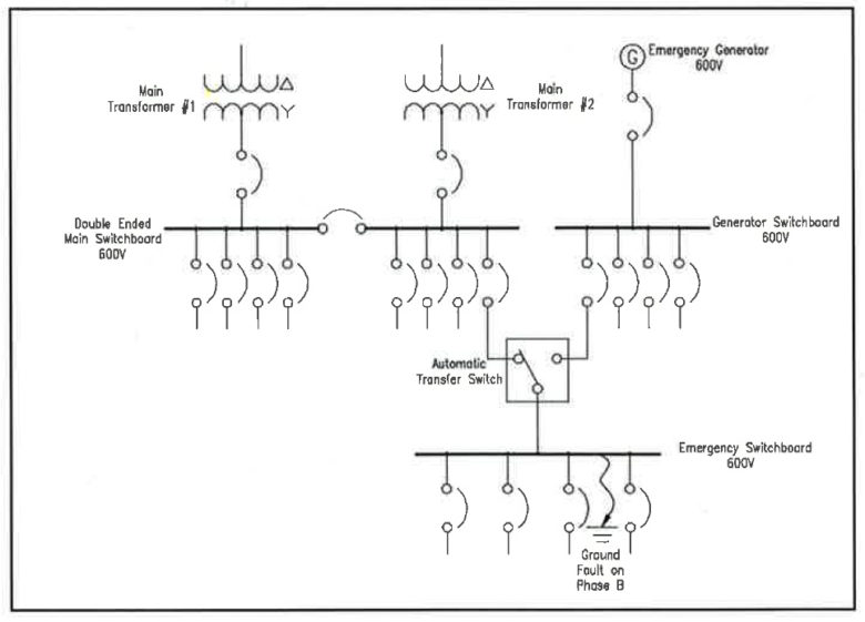
Fault Scenario
In a typical hospital, there will be a 600V normal power system and a 600V generator power system. The most critical loads are fed from the emergency power distribution, which is downstream of one or more transfer switches. The transfer switches get power from both the normal power system and the generator power system. In this scenario, a ground fault occurs in the switchboard downstream of a transfer switch. This fault could have a number of causes.
In the solidly grounded system, the ground fault results in a large current flow creating significant damage within the switchboard, vapourizing components and coating the inside of the switchboard with semiconductive residue. The high fault current subjects the upstream transformer to high stresses and causes the upstream breaker to trip. All power to the critical loads is lost. The loss of power is sensed at the transfer switch, which starts the emergency generator and transfers the critical load over to the generator. Since the switchboard is contaminated with residue from the previous fault, another fault occurs and this further damages the switchboard. It also stresses the generator with a high magnitude fault current and causes the generator breaker for the transfer switch to trip. The critical loads, including the emergency department and intensive care unit, are shut down and remain so until their feeders can be cut away from the failed switchboard, spliced and extended to another source of power – a process that takes many hours and leaves the critical loads on normal power only. The hospital is forced into emergency mode and must transfer critical patients to other areas of the hospital, which were not designed for their care, and in some cases to another hospital. Full restoration of the system requires replacement of the switchboard. This takes many months as switchgear is built to order.
In the resistance grounded system, the ground fault results in an alarm. There are no power interruptions, the main transformer is not subjected to the stresses of a fault, and the generator does not start, and is not exposed to a fault current. Most importantly, the damage to the switchboard is minimal, requiring the replacement of a single insulator, which is scheduled for a time when the hospital can accommodate the short shutdown necessary to perform the work.
Ground Current Detection
A major functional enhancement occurs when detection and alarm of ground faults is supplemented with monitoring of all the feeders to indicate which feeder is faulted and administer assistance for quickly locating the fault.
To provide assistance in locating a fault in highresistance grounded systems, the fault current is modulated by oscillating it between values such as 5A-10A, typically at one cycle per second. This is accomplished by changing the resistor value using a contactor, which has been called ‘pulsing’ in the industry. The pulsing is manually started. A flexible zero-sequence sensor or a clamp on the current transformer encircling all phase conductors is used to provide an oscillating signal to a handheld multimeter. Readings are taken on the faulted feeder moving away from the switchboard. The signal will disappear once the fault location is passed. Often, two or three measurements are sufficient to point to the fault location. Readings are taken from the outside of the grounded raceways, conduits or busways, while the system is energized and running. This technique has been in use for many years. It is quite effective for voltages up to 4,160V.
Tripping Up
The primary benefit of using high-resistance grounding is the faulted feeder does not need to be isolated on the occurrence of a phase to ground fault. While the faulted system continues to operate, there is a possibility that another phase to ground fault may occur on a different phase in some other weak spot in the distribution system. With the presence of a second fault, the fault current is no longer limited by the resistor and will be a higher magnitude fault. The zero-sequence sensors continue to monitor the fault current and if a significantly higher current than that limited by the resistor is detected, then the system recognizes that a line to ground to line fault exists and identifies the two feeders involved. Only one feeder breaker needs to be tripped to revert the rest of the system to a single fault condition. A level of priority can be assigned based on the relative importance of the feeders. The one feeder with lower priority is tripped. Fast operation provides protection and minimizes fault damage. Such systems have been in use for a long time and this first fault alarm and second fault trip is best applied to monitor specific loads.
Improving the System
On low voltage systems and systems up to 5 kilovolt (kV), high-resistance grounding provides a safer and more reliable distribution system. The arc flash hazard in the event of a line to ground fault can be eliminated and power continuity maintained. The performance of the distribution system can be enhanced by using high reliability neutral grounding resistors with low temperature coefficients, monitoring the neutral ground resistor continuously, using a pulsing system to find ground faults and using coordinated selective second fault tripping. In many applications, it is more beneficial to apply the neutral grounding resistor at the main bus. In such a case, the incoming supply feeders can be monitored for ground fault very cost-effectively by applying multi-circuit relays.
Authors
Ajit Bapat, P.Eng., Owner of Power Solutions
Nick Carter, P.Eng., Principal at HH Angus & Associates Ltd.
Sergio Panetta, P.Eng., Vice-president of engineering at I-Gard Corp.


