Is your facility and its electrical infrastructure prepared?

As electric vehicles (EVs) become more prevalent, they present a challenge for institutional-type facilities that have significant on-site parking, in terms of how to address the charging requirements of EV owners. Toronto’s Sunnybrook Health Sciences Centre (SHSC) is one such facility. With a three million ft2 campus and 4,535 parking spots, vehicular traffic exceeds 10,000 cars per day.

In 2018, SHSC was experiencing power outages in parking lots due to EV owners using adapters and extension cords to charge their vehicles from housekeeping receptacles. Recognizing the growing demand for on-site charging and wishing to promote green initiatives, SHSC investigated available incentive programs for an EV charging project.

HH Angus was engaged to assist SHSC in delivering this project. The first decision was to identify the type and number of charging stations that would best meet the needs within the established budget. One of the first decisions was which charging level to provide of the three levels available. Level 2 was selected, offering a full charge in four to six hours.

Key considerations for the supply of EV charging stations included physical construction and design features (for example, retractable charging cords were an important feature); service agreements; built-in wireless connectivity; and warranty coverage. It was also necessary to address the increased electrical load for the parking lots through power distribution upgrades and modifications to existing switchgear.

An important decision with direct impact on the installation design was the selection of dual-head EV charging stations, which allow two adjacent vehicles to be serviced by a single charging station. SHSC eventually installed 20 dedicated EV charging stations.

The entire project was successfully completed in approximately four months. By undertaking the necessary project planning, institutional facilities can help ensure their parking areas are ready to meet the requirements of EV owners and further support of green initiatives.

Philip Chow, P.Eng., P.E., was the lead engineer on the project and is a senior project manager at H.H. Angus & Associates Ltd. He specializes in electrical projects and construction in critical facilities and can be reached at philip.chow@hhangus.com.

Bavan Poologarajah,EIT., was the senior electrical designer on the project and worked on the project from initial concept design to final commissioning. Bavan has worked on a number of electrical projects in critical facilities and can be reached at Bavan.Poologarajah@hhangus.com.

cover photo of article

Does  your facility have a game plan to remain operational during an unexpected outage?

Stories of mass disruptions caused by electrical power outages make front-page news. We hear about extreme weather events, such as Hurricanes Katrina (2008) and Sandy (2012) and the Ontario Ice Storm of 2013 that cause widespread power outages due to damaged electrical utility infrastructure. International airlines have experienced disruptions with a multitude of stranded passengers due to electrical outages in the data centres that manage bookings. Cybersecurity and physical security have also become prevalent subjects with the continuous expansion of networked systems and recent acts of hacking and terrorism around the world. While difficult to quantify, executives understand the impact power outages have on corporate revenue, restart costs and poor public image with customers.

In the event of an unexpected electrical power outage, does your facility have a game plan to remain operational and restore systems? Does your operations group have a program that maintains emergency preparedness for electrical outages?

Internal power outages originating within a facility can be both short-term and long-term events. Short-term outages typically result from nuisance tripping, where overcurrent protection de-energizes a circuit due to an abnormal event, an increase in electrical load, the addition or replacement of equipment with new ratings, or incorrect protective settings. In most instances, short-term outages do not result in any significant equipment damage, and power is restored after the cause is identified and subsequent diagnostic tests are performed. Long-term outages can result from a variety of causes and typically result in permanent equipment failures and damage that renders a portion of a distribution system inoperable. When a long-term outage occurs, facilities fortunate enough to have redundancy built into their distribution system can rely on alternative feeders, transformers or circuits with spare capacity to restore power in the interim. Without the luxury of built-in redundancy, temporary solutions and temporary equipment rentals may be required, while replacement equipment is being manufactured (a process that can take upwards of 20-plus weeks). In order to fully appreciate the possibility and impacts of unexpected internal power outages, let’s consider a few case studies.

Short circuit

Electrical work can create the potential for electrical hazards, accidents and associated power outages. In this case study, an electrical contractor was expanding on a newly installed 15,000V (15kV) distribution system. A dedicated electrical-service space was being constructed in a critical, process-based facility in British Columbia. The contractor was in the process of running a 15kV feeder circuit to connect an existing load to the new distribution system and new medium voltage cables had been run in anticipation of an upcoming shutdown to make the final connections. Prior to the shutdown, the contractor was performing some final checks within the 15kV switchgear and accidently energized the 15kV circuit. The new MV cables, which were left unterminated and coiled together, became energized and created a three-phase bolted fault. The accidental energization resulted in a short-circuit event of about 10,000A and was near the maximum fault level stipulated by the local utility. Multiple medium voltage circuit breakers tripped as a result of the fault, including a main breaker in the service entrance switchgear for the site. The facility’s standby generators came online, due to the tripped circuit breakers and powered the facility for a number of hours, until the a procedure to properly isolate the circuit was implemented and utility power was restored. Fortunately, no injuries occurred and a subsequent assessment revealed that no damage to equipment or cables occurred, with the exception of the cable ends, which were cut back several inches.

Failed transformer

Facilities often rely on service groups to perform routine electrical tests, circuit switching and isolation requests. The exact switching procedure is typically left up to the service group and they are responsible for operating distribution equipment. In this case study, a service contractor was manually switching between utility power and standby generator power via a set of 480V circuit breakers. The system was placed into manual operation, utility power breakers were opened, standby generation was brought online and generator breakers were closed to provide power to the switchboard. When it came time to return to utility power, the utility power breaker was inadvertently closed, while the standby generators were still powering the switchboard. The switchboard did not have any synch-check protection, paralleling equipment or interlocks. The individual generator breakers tripped open several seconds after the unintended paralleling condition was created. Unfortunately, large magnitude currents had circulated within the distribution system, before the generator breakers tripped. These large magnitude currents created significant magnetic forces, which damaged bus work in a dry-type transformer that was close coupled to the switchboard. The bus work was bent outwards and insulating paper covering a portion of the bus was dislodged, creating a condition where uninsulated bus was bent into contact with the grounded steel frame, supporting the core and coil assembly. The resulting line to ground fault melted the entire bus connection, until the phase to ground fault was eliminated and the bus connection was no longer in contact with the steel frame. Fortunately, proper safety procedures had been followed and no one was injured in this incident. The switchboard was supplied with power from a redundant transformer and the damaged transformer was permanently removed from service. The facility subsequently shifted downstream loads to other distribution within the building, to further offload the remaining transformer.

Latent installation defects

Electrical failures can also occur unexpectedly within a distribution system, without any precipitating factors such as electrical work or switching operations. A variety of recent cases come to mind, with causes that include latent installation defects, utility supply issues and failures related to aging electrical infrastructure. A critical facility, in the Greater Toronto Area, experienced a localized extended power outage for several weeks, when a dry-type transformer unexpectedly failed. The dry-type transformer provided essential power to both occupied areas in the building and critical process-based loads. The transformer had been recently upgraded to a new energy-efficient model and the replacement core and coil assembly had been site installed, due to space limitations and access requirements for a newly manufactured unit. The failure analysis confirmed that low-voltage control wiring for power metering had been installed in close proximity to uninsulated 5kV buswork and a flashover had occurred due to the insulation rating of the wiring and insufficient physical clearance. Operations were shut down in the affected area until a refurbished transformer was sourced and installed.

In another example, an Ontario- based electric utility experienced an outage to one phase in a distribution circuit, when parallel fuses for one of the phases in a disconnect switch unexpectedly blew. The utility replaced the blown fuses and restored power within several hours. However, by this time the facility had determined that several 30 hp motors, critical to the central plant’s chilled water and condenser water system, had burned out due to the single-phasing condition and inadequate motor overload protection. Mechanical services were interrupted for 15 hours while motors were replaced. In yet another example, an underground 5kV distribution cable, in an institutional campus, unexpectedly failed after approximately 25 years in service. Temporary generators were brought in for a week, until a portion of the failed cable could be removed and re-fed with replacement cable. While the cable had not yet reached statistical end-of-life conditions, it was determined that the early failure was attributed to physical damage, which had reduced the cable’s anticipated life expectancy.

Modes of failure

How can an operations manager plan for an unexpected electrical outage in their facility? To start, a well-structured preventative maintenance program and an infrastructure review can help diagnose potential risks. Is equipment being maintained and are recommended diagnostic tests being performed? Equipment should be reviewed for age and reliability. Consideration should be given for redundancy in the power distribution system and how the failure of a particular component could affect continued operation. Taking meter readings on a frequent basis will confirm if there has been any load growth and how load is segmented throughout a distribution system. If metering is unavailable, consideration should be given for installing permanent metering or taking readings with a portable meter. Operational data can be used to expand on a facility’s electrical single-line diagram and performing a detailed review can determine options for supporting load in emergency situations. Emergency scenarios should include how critical loads are supported during an extended utility outage, how load can be supported during equipment failures (transformers, switchboards, panels and main feeders), points in a distribution system for connecting a temporary generator and options for interlocked tie connections. Abbreviated single line diagrams for modes of failure and electrical load data can be used to create a standard operating procedure (SOP), in the event of an unexpected power outage. A well-developed SOP will include detailed, step-by-step operations to help diagnose an electrical outage, isolate faulted equipment if applicable and restore power using alternative means, if available. Photographs of equipment should be included and operating switches, buttons and HMI screens should be identified. Having a guide readily available will increase response times and decrease downtime.

Plan ahead

To complement the effectiveness of standard operating procedures, any work performed on a power distribution system should be subject to a detailed method of procedure (MOP). A typical MOP will outline a step-by-step procedure for work being performed and includes information on demarcation of work (who is doing what?), the duration of tasks, a back-out plan to deal with the unexpected occurrences and a list of emergency contacts. A dry-run of switching operations and load transfers should be performed in advance of a planned shutdown, especially when a number of complex switching operations and load transfers are involved. Operations staff should actively participate in the process, as this will further develop familiarity with a power distribution system and mitigate risk when electrical work is being performed. Consideration should also be given to providing regular training sessions on electrical systems for operators. Training should focus on the topology and equipment in the distribution system, facility procedures (SOPs and MOPs), preventative maintenance requirements and general troubleshooting practices. Having well-trained operations staff will not only ensure that a facility’s first responders can effectively deal with issues when they arise but also ensure outside contractors follow an approved procedure before commencing work.

Unexpected electrical outages in a facility can be caused by a variety of factors, including electrical work, routine switching operations, issues with the incoming utility supply, or aging infrastructure. A proactive approach to managing an electrical power distribution system and maintaining emergency preparedness should include: a well-developed preventative maintenance program; the creation of SOPs to identify an approved response to emergency scenarios and to troubleshoot issues; MOPs for all electrical work, including preventative maintenance and isolation procedures; and having regular training sessions for operations staff. Undertaking a detailed needs assessment will help a facility review procedures currently in place, identify any shortcomings with existing practices and provide opportunities for improvement. Creating documentation for SOPs, MOPs and training will typically involve a detailed review of existing systems, creating a site-specific set of procedures, and drawing upon industry standards and best operational practices. By investing in a plan for emergency preparedness, operations managers can equip their staff with the knowledge to deal with the next electrical outage, thereby increasing response times, decreasing downtime and ensuring their facility remains operational.

Published in the Canadian Consulting Engineering Magazine September 2017 Page 23-24. 

Authors :

Phil Chow, P.Eng., P.E., Senior project manger & electrical engineer at HH Angus

Mathew Walker, P.Eng., Senior electrical engineer at TELUS Communications

The Toronto Zoo constructs a new Wildlife Healthcare Facility

The Toronto Zoo is Canada’s premier zoo and home to over 5,000 animals, including invertebrates and fish, representing 460 species from a variety of geographical regions around the world. Encompassing approximately 710 acres, the Toronto Zoo is Canada’s largest zoo and is divided into seven zoogeographic regions, ranging from the Americas, to Africa, Australasia and Eurasia.

The campus includes numerous support facilities dedicated to animal care, operations, maintenance and veterinary services. With the existing veterinary facilities dating back to 1974, the Toronto Zoo recognized the need for redevelopment and expansion. The mandate for the new Wildlife Health Centre is to provide a state-of-the-art facility for veterinary services, that will further the Toronto Zoo’s commitment to wildlife health, nutrition, species survival research, conservation and education.

Planning for the new centre commenced in 2011 with Diamond Schmitt Architects, in collaboration with animal healthcare specialists Design Level, leading the team and preparing the architectural design for the new facility.

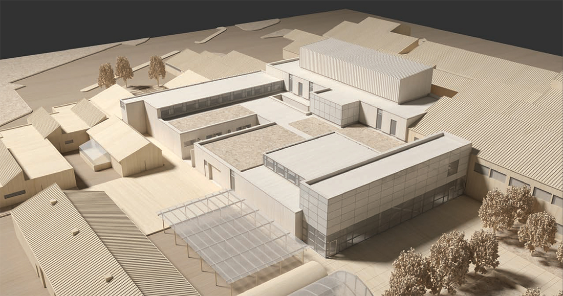
With a total gross area of 32,000 sq. ft., the new two-storey building would be located in the centre of the Toronto Zoo’s existing animal support complex and would be constructed in the footprint of the existing veterinary services building. Adjacent service buildings, including the existing Research, Animal Holding, Quarantine, and Conservation and Biology facilities, would connect to the new Wildlife Health Centre.

Design considerations

The functional program for the new centre would have to meet a variety of objectives, including: meeting the needs of the different animal species, taking into account diverse environmental requirements for the various habitats, providing a layout that promotes the effective delivery of ongoing healthcare services and meeting the requirements of the veterinary professionals who perform these services. Eric Lucassen, Project Architect at Diamond Schmitt, notes, “Working with the Toronto Zoo to create functional programming that supports animal healthcare, while meeting the unique habitat requirements for the various animals, involved a detailed planning process.”

The facility program for the Wildlife Health Centre is split over two floor levels and consists of animal treatment and surgical areas, diagnostic imaging, an intensive care unit, laboratories, animal holding areas, offices and support spaces, and a public viewing area. Animal holding areas are further divided into spaces for small and large animals, which require ceiling-high caging to provide safety for the staff.

Surgery and diagnostic imaging spaces are centrally located and are accessible via wider corridors to facilitate the easy transport of animals into these areas. A garage is located adjacent to the surgery area, and an electric hoist and hoist beam runs from the garage to the surgery area to help the transport of larger animals.

The majority of two-storey rooms have large clerestory (windows just below the ceiling) around the perimeter of the spaces. This architectural feature allows a significant amount of daylight to enter the interior of the building and creates the feeling of being in an open, natural environment. Laboratories and support spaces are located in close proximity with animal care areas to minimize travel distances for support services.

Mechanical considerations

Given the varying functionalities and diverse environmental requirements of the different spaces, a number of innovative applications of mechanical and electrical systems were incorporated in the building’s design. The holding area for fish and reptiles required that tropical temperatures be consistently maintained throughout the year, maintaining 100% relative humidity. Electric heat tracing cable, specifically modelled for the application by Tyco Thermal Controls, was installed in the slab to ensure that the temperature in the area would be maintained during winter months. While the electric heat tracing cable maintained a heat pad for reptiles, additional radiant floor heating was used to maintain the environment and create general floor comfort for animals.

Ventilation systems in animal care areas throughout the facility rely on a continuous 100% fresh air supply, with no return air, to ensure that contaminants and excrement are not circulated through the ventilation system. A heat recovery system was provided on the exhaust air system to increase energy efficiency. Animal surgery areas utilize a dedicated supply air system, which incorporate air change requirements and filtration comparable to the requirements for a human healthcare facility. By utilizing a separate, dedicated supply air system for surgery areas, energy efficiency is maintained in areas that require fewer air changes per hour.

Other energy efficient elements in the design included the use of low flow plumbing fixtures, roofing and landscaping features that promote heat island reduction for the site and the use of insulated glazing that provides an optimal balance between daylighting and heat transfer.

Electrical and lighting requirements

Unlike hospitals where patient care equipment is standard and there are prescribed standards for electrical circuiting requirements, animal care areas have speciality equipment items, and require multiple dedicated circuits and receptacles. Additionally, animal care areas were considered wet environments, due to the frequent washing that occurs after animals are returned to their habitats.

Ground fault circuit interrupter (GFCI) receptacles were used in these areas to maintain electrical safety. Lighting fixtures throughout the facility were selected to provide both illumination requirements for animal care and were vapour tight, to maintain infection control practices and protect luminaires from inadvertent spray during cleaning.

Occupancy sensors and multiple light switches were used throughout the facility to give users a wide range of automatic and manual lighting control, which allow lights to be turned off when there is enough daylight present through windows and clerestory.

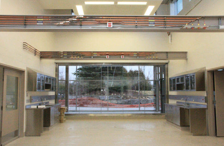
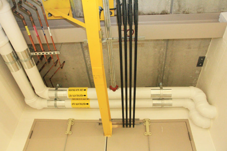
To avoid interference with full height cages, architectural clerestories, and to minimize the likelihood of interaction with animals, overhead mechanical and electrical services were routed outside of animal care areas and confined to corridor spaces. This created several installation coordination issues that were resolved by the contractor, via the creation of detailed interference drawings during the construction phase of the project.

Nearing completion

The project was competitively tendered and awarded to Gillam Group Inc., with construction commencing in February 2015. The new building is in the final phases of construction and is scheduled to be complete during the first quarter of 2017.

Working on an animal healthcare facility designed to accommodate a variety of different species, with diverse requirements, proved to be a unique challenge.

While healthcare standards are readily available for hospital construction, there are minimal design and construction standards available for this type of animal care facility. Environmental standards established by the Canadian Council on Animal Care and general healthcare design experience contributed to the overall design.

Furthermore, involving the users throughout the project was critical in identifying the unique needs of various animal groups. Eric Lucassen notes, “Having the Toronto Zoo’s veterinary staff provide input into specific design requirements at every step of the project helped the design team develop innovative solutions to provide an enhanced animal care environment.” CCE


Philip Chow, P.Eng., P.E. is a senior project manager at H.H. Angus & Associates Ltd., Philip.Chow@hhangus.com